Sample drawings
See a drawing sheet before you order
DDG-M-101 is an example Tier 4 equipment layout, drawn from the same simulated plant as the demo on the home page. Open it on screen, or print it full size.
Drawing register
One sheet, three files
The SVG is the on-screen version, on navy like the rest of the site. The PDFs are set up for printing: white background, vector linework, searchable text, and the sheet scaled to fit inside the margins.
| Sheet no. | Title | Format | Sheet size | Download |
|---|---|---|---|---|
| DDG-M-101 | Existing conditions — equipment layoutExample · simulated plant, not client data | SVGVector, on navy, for screens | ScreenScales to any width | Download DDG-M-101 as SVG,40 KB |
| DDG-M-101 | Existing conditions — equipment layoutExample · simulated plant, not client data | PDFVector, on white. Tabloid printers and on-screen review | ANSI B17 × 11 in | Download DDG-M-101 as ANSI B PDF,32 KB |
| DDG-M-101 | Existing conditions — equipment layoutExample · simulated plant, not client data | PDFVector, on white. Full-size plots on a wide-format plotter | ARCH D36 × 24 in | Download DDG-M-101 as ARCH D PDF,32 KB |
Fabrication-critical tie-ins, flange locations, anchor bolts, and tight-clearance dimensions need separate verification before fabrication or installation, quoted separately. Verification rule
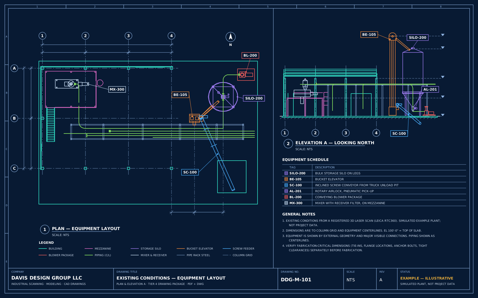
On this sheet
- Plan view
- Column grid A–C and 1–4, bay and overall dimensions in feet and inches, equipment located from the grid.
- Elevation A, looking north
- Elevation markers for the slab, mezzanine, eave, silo and elevator head, with EL 100'-0" at top of slab.
- Tags and schedule
- Each tagged item (SILO-200, BE-105, SC-100 and the rest) is listed in the equipment schedule.
- Colour by object
- Linework follows the same colours as the 3D model views, so the sheet reads against the model.
- Notes and title block
- General notes, and a title block with the sheet number, scale, revision and status.
A project’s sheet list, views and level of detail are agreed in the proposal.
Formats
What each file is for
The sample above covers drawings. Point clouds and models ship too, in formats set in the proposal, so ask for the ones your team already opens.
| Format | What it’s for |
|---|---|
| Point cloudSupplied in one agreed format per project. | |
| RCP / RCSAutodesk ReCap project | Attach directly in Navisworks, AutoCAD, and Inventor |
| E57ASTM E57 | Vendor-neutral exchange for other platforms |
| LAS / LAZASPRS LAS | GIS and open-source tools |
| 3D modelNative Autodesk files plus an agreed exchange format, defined in the proposal. | |
| IPT / IAMAutodesk Inventor parts & assemblies | Equipment and mechanical assemblies, with references when contracted |
| NWD / NWCAutodesk Navisworks | Coordination, clash review, and design walk-throughs |
| STEPNeutral 3D exchange | Hand-off to other CAD platforms |
| Drawings (Tier 4)Included with the Tier 4 drawing package. | |
| DWGEditable AutoCAD drawings | Plans, layouts, elevations, and sections you can build on |
| PDFPlotted drawing set | Review, markup, and distribution |
Need drawings like this of your plant?
Send the facility type, the approximate area, and the plans, elevations or layouts you need. The sheet list and scope are set in a written proposal.